Prev:
null
Jun 25,2026
Pageview: 4
Picture this: a critical 15kW compressor motor at a packaging plant randomly trips offline. No obvious overload, no clear fault code. After two service calls and a fried winding, the technician finds the culprit—a voltage protection device installed with the neutral wire connected to the wrong terminal. The protector never saw the phase unbalance that was quietly overheating the motor for weeks.
That scenario plays out more often than you’d think. Three‑phase voltage protectors are the last line of defense against grid anomalies, yet many end up as expensive ornaments on a DIN rail simply because they were installed in a hurry. To get genuine protection instead of a false sense of security, steer clear of these four recurring mistakes.
If your facility already relies on voltage‑sensitive assets—think CNC spindles, refrigeration racks, or water treatment pumps—you may want to take a closer look at the protection philosophy behind the panel door. A deeper understanding often starts by exploring modern protection designs that prioritize configurability.
In a 4‑wire Wye system, the neutral carries the unbalanced current. If your voltage protector expects a neutral reference and you leave it floating, the device can’t accurately measure phase‑to‑neutral voltages. Undervoltage on one phase may go completely unnoticed.
The opposite mistake happens with 3‑wire Delta supplies. Some installers reflexively jump a neutral terminal to ground, introducing a ground‑loop that corrupts the voltage measurement. In one food processing plant, this phantom “neutral” caused a protector to trip constantly during motor starts, even though the supply was rock‑solid.
Get it right: Always check the protection device’s data sheet. If it says “suitable for 3‑phase 3‑wire or 4‑wire,” confirm which internal jumpers or DIP switches must be set before power‑up. Drawings matter—don’t assume your colleague left the factory default in place.
Off‑the‑shelf voltage protectors often arrive with pre‑set under‑voltage and over‑voltage limits—say 185V–260V for a 230V system. That wide window works for resistive loads like heaters, but it’s alarmingly loose for modern electronics that tolerate only ±10%. A server UPS may run on battery multiple times a day while the protector stays blissfully silent.
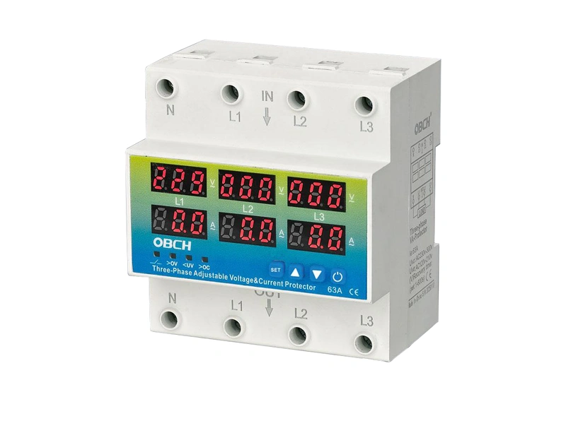
Rather than gambling with fixed thresholds, many maintenance teams switch to a device with adjustable trip settings. Instead, using a device with settable trip points, often referred to as an adjustable voltage protector, allows you to match the protection curve to your equipment’s actual tolerance band. This becomes vital in regions where grid voltage regularly drifts upward during periods of high solar feed‑in.
The fix is simple: if your load’s nameplate states “undervoltage trip at 200V,” set the protector to 200V, not to the generic 185V default. An intelligent protection unit that lets you dial in your own limits removes the guesswork and can eliminate nuisance trips or missed faults.

“The green LED is on, so we’re good.” That mindset is the enemy of reliability. A voltage protector can power up normally yet still fail to open its relay when a phase is lost—because the trigger circuit relies on a derived neutral that was never tested under fault conditions.
The only way to be sure is to simulate the exact scenarios the protector is supposed to guard against. Use a three‑phase injection tester or, at a minimum, intentionally disconnect one phase and measure the output contact response. Repeat for phase reversal (if the protector includes rotation monitoring), under‑voltage, and over‑voltage. Document the trip and re‑close times.
IEC 60255‑1 suggests functional testing of measuring relays during commissioning, and voltage protectors fall squarely under that umbrella. Skipping this step is like installing a smoke detector without ever pressing the test button.
A voltage protector installed inside a non‑ventilated stainless‑steel enclosure on a rooftop can see internal temperatures exceeding 60°C by noon. Most industrial‑grade electronics are rated to 55°C operating; push beyond that and the voltage sensing accuracy drifts, sometimes by several percent. Suddenly, a perfectly calibrated unit triggers false trips, eroding operator trust.
Vibration is another silent killer. Direct‑mounting a protector on a large chiller compressor panel without isolating the DIN rail leads to fretting corrosion on terminals. Over time, the relay contacts develop micro‑openings, and the downstream contactor starts chattering—an expensive cascade.
A three‑phase monitoring device built for harsh utility and machinery environments will list its environmental specs clearly: operating temperature range, humidity class (e.g., IEC 60721‑3‑3 class 3K5), and vibration rating. Compare those numbers to the actual installation location before you drill the first hole. If the ambient is borderline, consider active cabinet cooling or a remote‑mount display unit.
None of these mistakes stem from faulty equipment—they’re process and knowledge gaps. A simple commissioning checklist can catch all four: verify the neutral scheme, set thresholds to match the load, simulate faults, and log the environmental limits of the spot you picked.
When your equipment stack includes variable‑speed drives, servo controllers, or medical imaging gear, the cost of a missed voltage event dwarfs the price of getting the protection right. Upgrading to a modern adjustable voltage protector eliminates the fixed‑threshold compromise and gives facilities the flexibility to dial in parameters as processes evolve. That shift alone can reduce no‑fault‑found service calls by double‑digit percentages.
If you want a starting point for a more professional setup, Obch’s protection line brings together field‑configurable thresholds, wide‑range supply compatibility, and compliance with international references such as IEC 60255‑1. Their documentation also includes ready‑to‑use commissioning forms that make injection testing repeatable.
Disclaimer: This article offers general guidance based on common field experience and applicable standards. Always consult the manufacturer’s installation manual and follow local electrical codes for your specific installation.